

Summary of information related to WP6
November 10, 2010
A performance specification is essential to provide a framework for all the technical activities to be undertaken during the EISCAT_3D Preparatory Phase. The preparation of an initial performance specification was already undertaken at the start of the FP6-funded EISCAT_3D Design Study. This needs to be revisited and updated in the light of the Design Study findings, and kept under continuous review as the Preparatory Phase progresses. During this phase of the project, the trade-off between the desired system performance and the level of resources likely to be available to implement EISCAT_3D will become evident. In such a situation, a good definition of acceptable system performance will be essential in making decisions about what kind of system is actually likely to be implemented.
In addition to the specification of hardware performance, EISCAT_3D will also incorporate a range of new measurement principles made possible not only by the innovative phased array design, but also by the innovative types of signal processing, coding, data handling and data analysis which will be used on the new hardware. In order to optimise the benefit which the future users of EISCAT_3D can derive from these new possibilities, a handbook of measurement principles will be prepared, in order to outline the optimum strategies for the use of the new facility. This handbook will be used as the template framing the specification of the system software being developed in WP10, WP11, WP12 and WP13 and, in that sense, will complement the earlier specification which focused on hardware performance.
The main aims of this activity are:
Revisit the performance specification produced in the FP6 Design Study stage to take account of the Design Study findings and incorporate any ideas which have emerged since the end of the Design Study.
Produce a handbook of measurement principles, setting out how the system performance can be optimised by the application of innovative concepts in signal processing, coding, data handling and data analysis, which will be used thereafter as a framework for software and experiment development in EISCAT_3D.
Update and maintain the performance specification so that it provides a continuing resource for all of the technical work packages to determine details of acceptable system performance and hence define their required outputs.
The output of this package will be a set of performance specifications, covering all elements of the proposed system and capable of delivering the science goals defined in WP3. In particular, it will be ensured that these Work Packages provide input to WP14 on issues of reliability and quality control for components which are required to operate in large volumes.
Completing an initial version of the Project Specification Document will be the first task for the Technical Advisory Committee. The Performance Specification Document will be critical to some nationally-funded activities, and the leaders of these packages will be included in this consultation.
Deliverables
Deliverable 6.1: Initial Performance Specification Document
August 11, 2011
The Performance Specification Document describes the kind of system that is wanted from the EISCAT_3D project. It consists of three documents:
Concept Document
A document detailing a strategic overview of the EISCAT_3D instrument concept, design, planned performance characteristics, and capabilities.
System Design Document
A detailed design philosophy dpcument that facilitates communication between scientists, engineers and other team members. It defines the level at whish system choices and trade-offs can be made.
Engineering Specification Document
A document containing the specification of engineering requirements for the
EISCAT_3D system.
In this initial version of the PSD only the first document is finished – the other two are only skeletons at this stage. The documents in their present form are compiled into one pdf-file to form Deliverable 6.1.
The PSD will continuously be updated throughout the project.
Deliverable 6.2: Initial version of the handbook of measurement principles
October 14, 2011
A handbook of measurement principles for incoherent scatter radar systems is produced as part of the EISCAT_3D Preparatory Phase project. This handbook is setting out how the system performance can be optimised by the application of innovative concepts in signal processing, coding, data handling and data analysis. The plan is that this handbook will be used as a framework for software and experiment development in the future EISCAT_3D system.
The initial version of the handbook has been prepared in order to deal with the most important pieces of information which were missing or partly incompletely treated in the first design study of the EISCAT_3D radar. It forms Deliverable 6.2.
The handbook will be expanded and iterated as the study continues throughout the project.
Deliverable 6.3: First version of an integrated performance specification
June 12, 2012
The integration of the initial Performance Specification document with the first version of the updated Science Case and the first version of the Handbook of Measurement Principles is a comprehensive Performance Specification covering the hardware and software elements of the new system, and showing how the science goals can be addressed:
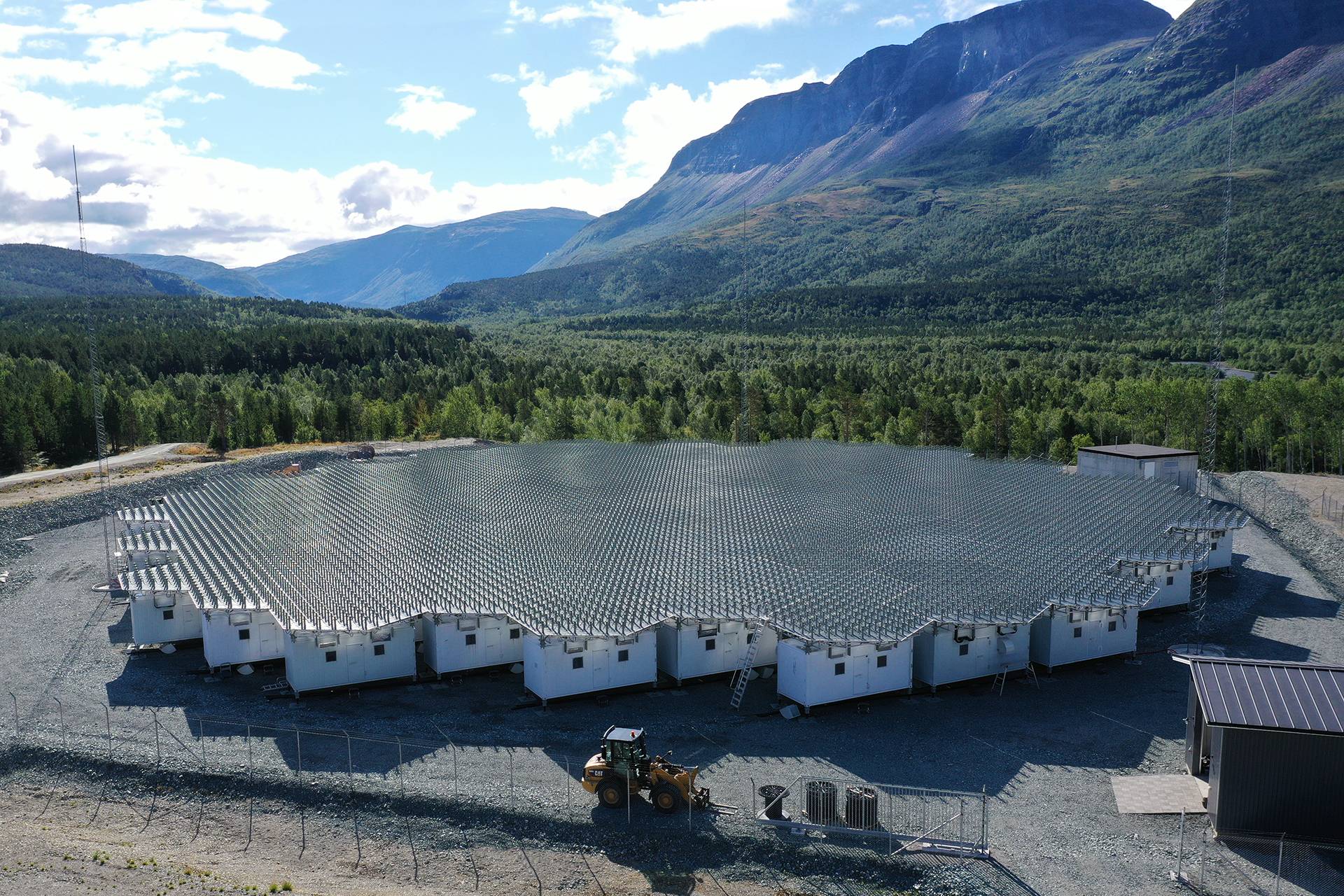
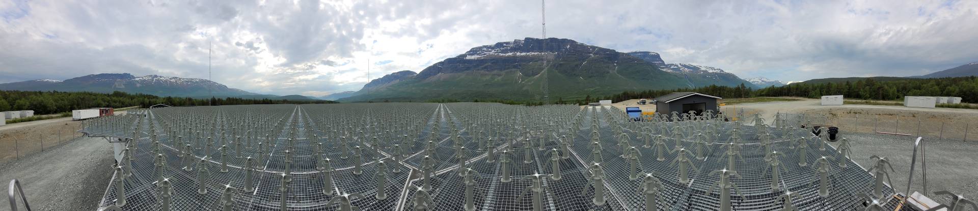
The EISCAT_3D facilities will comprise one core site and four distant sites equipped with antenna arrays, supporting instruments, platforms for movable equipment and high data rate internet connections. Two pairs of distant sites with primary receiving capabilities will be located at different baseline distances within roughly 90 km ? d ? 280 km from the core site. The most favorable geometry for tri-static observation, for the four remote sites, is along two baselines, running orthogonally to each other from the central site. The core site with full transmitting and receiving capability will be located within roughly 100 km of a point at 69°N 20.5°E.
The mono-static core array consists of antenna elements having transmitting and receiving capability. Distributed receivers located added at close distance at the core site allow for testing bi-static measurements. This set-up allows modular construction as well as first scientifically exploitable results at an early stage.
The core site will comprise:
Phased-array of order of 10000 elements including both Tx and Rx capabilities
RF signal generation equipment and RF power amplifiers
Transmit/receive switching system
Beam-steering systems for transmission and reception
Incoherent scatter receiver subsystem
Outlier elements
Receive-only phased-array for narrow receiving beams and in-beam interferometry
Beam formers
Time and frequency synchronisation equipment
Digital signal processing equipment
Built-in test equipment
The total size of the central site will exceed 1 km, given that the dense inner core of antennas will be accompanied by a sparsely distributed array of outlying antennas.
The remote sites will comprise:
Phased-array antennas with associated receivers
Beam-formers
Time and frequency synchronisation equipment (performance clock and clock distribution systems)
Digital signal processing equipment
Built-in test equipment
The approximate size of a remote site will be around 300 m squared.
The transmitter parameters are:
Centre frequency
233 MHz (or < 233 MHz if need to be shifted)
Peak output power
10 MW
Average Power
2.5 MW
Instantaneous –3 dB power bandwidth
5 MHz
Pulse length
0.5–3000 microseconds or continuous
Pulse repetition frequency
0–3000 Hz (also irregular pulse sequences being possible)
The receiver parameters are:
Centre frequency
233 MHz (or centered around receiver frequency)
Instantaneous bandwidth
+/- 15 MHz at core site, preferably also at other sites at least +/- 5 MHz
Overall noise temperature
<50 K referenced
Cable length
not much longer than 5m
Spurious-free dynamic range
>70 dB
Deliverable 6.4: Annual status report on the Performance Specification activity
December 5, 2013
The integrated performance specification is kept under continuous review with regular iterations to incorporate developments in the other Work Packages. The current version of the document is posted annually as a deliverable of Work Package 6.
In October 2012, the project summarised the current status of the Performance Specification in two tables describing the base-line design and illustrating the performance of the baseline configuration.
The EISCAT_3D instrument will consist of 5 phased-array antenna fields for transmission (Tx) and reception (Rx) of 233 MHz radio waves. Total transmitted power at the core site will be 10 MW and at least one remote site will have transmission capability of about 1 MW. Digital control of the transmission and low-level digitization of the received signal will allow for instantaneous beam-swinging, and multiple simultaneous transmit and receive beams, without motion of mechanical structures. The sites will be equipped with smaller outlying antenna arrays that will facilitate aperture synthesis imaging to acquire sub-beam transverse spatial resolution. This will give the EISCAT_3D radar unmatched power agility and flexibility. The baseline design suggests a core site that will be located close to the intersection of the Swedish, Norwegian and Finnish borders and four receiving sites located within approximately 50 to 250 km from the core.
The EISCAT_3D concept permits continuous pre-scheduled operations and fast and automatic switching of observation modes. It offers advanced capabilities to study atmospheric phenomena on scales of hundreds of kilometers to hundreds of meters. Atmospheric monitoring at 70-1200 km altitude is only limited by power consumption and data storage.
To quantify the improvements in performance it is illuminating to compare the integration time required to obtain plasma parameter estimates with the same accuracy with the current UHF and the new EISCAT_3D systems. The larger total transmitter power is required for most of the new observation modes, since the new system has many new features that the current EISCAT instrument does not have. These measurement modes offer major advantages of EISCAT_3D also compared to other systems.
The base-line design, like the Performance Specification, will be updated following the progress of Work Package 6 as well as of other workpackages and based on the requirements imposed by the schedule for construction and funding.
Deliverable 6.5: Annual status report on the performance specification activity
December 6, 2013
The integrated performance specification is kept under continuous review with regular iterations to incorporate developments in the other Work Packages. The current version of the document is posted annually as a deliverable of Work Package 6.
The EISCAT_3D facilities will comprise one transmit/receive core site and four distant, primarily receive sites equipped with antenna arrays, supporting instruments, platforms for movable equipment and high data-rate Internet connections. The receive sites will be arranged at a pair of closer locations to the core to provide high resolution E-region vector drift measurements and another pair of locations spaced further from the core for F-region vector coverage over a larger region. The two pairs of receive sites with will be located at baseline distances within roughly 90 km ? d ? 280 km of the core site. The core site with full transmitting and receiving capabilities will be located within roughly 100 km of a point at 69 degrees North and 20.5 degrees East, well situated for auroral zone research.
The mono-static core array will consist of antenna elements having transmitting and receiving capabilities as well as relatively closely located antennas to support aperture synthesis imaging for probing within the transmitted beam. Each element will have full polarization control on transmit and full polarization measurements on receive. The polarization measurement capability will also be available at all receive sites. Synchronization between the subsystems will be handled via a combination of short latency internet connections, local GPS-based real-time clocks, stable clock oscillators at each site, and a high-accuracy clock distribution system at each site (most likely based on an extension of the IEEE-1588 protocol). Each site will also contain sufficient processing capacity for digital beam forming, local storage of intermediate measurement products, and processing capacity for near real-time plasma parameter extraction.
The entire system will be configured for unattended remote operations, though there may be the need for a very small staff, especially at the core, for safety reasons. The sites will, however, also have limited infrastructure to support scientific and technical visitors for research campaigns.
The core site will comprise:
- Phased-array, polarization-flexible antenna with on the order of 10,000 elements (actual number of antenna elements based on optimization of system costs)
- Distributed RF signal generation exciters, two per antenna element, amplitude and phase capable
- Distributed RF power amplifiers, 2×500 W per antenna, amplitude and phase modulation capable
- Distributed transmit/receive switching
- Distributed low noise amplifiers, total added noise goal is <50 k=”” br=””> Receive-only outlier elements for narrow receiving beams and in-beam interferometry
- Beam forming system
- Time and frequency synchronization equipment
- Digital signal processing equipment (in addition to beam forming)
- Built-in test and monitoring equipment
- System calibration equipment
- Power control and distribution equipment
The total size of the central site will exceed 1 km, given that the dense inner core of antennas will be accompanied by a sparsely distributed array of outlying antennas. The dense inner core will require approximately 70 m × 70 m of space, with an additional buffer for safety.
The remote sites will comprise:
- Phased-array, polarization-flexible antenna with on the order of 10,000 elements (actual number of antenna elements based on optimization of system costs)
- Distributed low noise amplifiers, total added noise goal is <50 K
- Beam forming system
- Time and frequency synchronization equipment
- Digital signal processing equipment (in addition to beam forming)
- Built-in test and monitoring equipment
- System calibration equipment
- Power control and distribution equipment
The transmitter parameters are:
- Centre frequency near 233 MHz
- Peak output power: 1000 W per antenna element, totaling approximately 10 MW
- Instantaneous: 3 dB power bandwidth >5 MHz
- Pulse length: 0.5–3000 microseconds
- Duty cycle: 0-25%
- Interpulse period: > 100 microseconds (fully flexible pulse sequences)
- Capability to transmit arbitrary phases and amplitudes
- Stable gain and delays over the specified temperature range
The receiver parameters are:
- Centre frequency 233 MHz (or centered around transmitter frequency)
- Instantaneous bandwidth: +/- 15 MHz at core site, preferably also at other sites at least +/- 5 MHz
- Overall added noise temperature (above sky noise): <50 K referenced
- Spurious-free dynamic range: >70 dB
The system parameters will be selected such that, over the multi-static field-of-view, the resolution along the transmitted beam direction(s) can be made better than 100 m at any altitude and the horizontal (transverse) –3 dB resolution at 100 km altitude is better than 100 m. The beam generated by the central core transmit/receive antenna array will be steerable out to a maximum zenith angle of the order of 40 degree (60 degree with lower performance) in all azimuth directions. The beam from the central core antenna array will be steerable into any new pointing direction on timescale better than 1 microsecond through coordinated switching of the exciters.
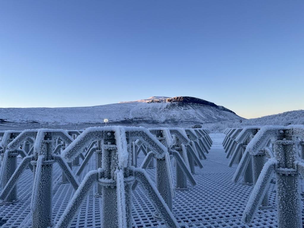
Environmental considerations, maintenance costs as well as possible malfunction during ice and snow coverage need to be considered for antenna design. Changes in performance due to ice and snow coverage need to be within a range that can be compensated by adjusting the measurement parameters. Ideally the antenna performance does not require a solid ground plane. The configuration shall be as insensitive as possible to snow conditions, particularly with respect to snow accumulation.
The sites shall be equipped with facilities for Optical Cameras, Ionosondes and Data Storage. Sites should be prepared over a range larger than what is needed for initial instrumentation in order to have the space for further instruments and in order for further construction works not disturbing measurements. Site infrastructure needs to account for shielded mitigation of RF interference, especially at the core but also at the remote locations.
Optical Cameras
Support for basic optical instrumentation at the core and selected distant sites will allow the observation of auroral or airglow emissions and Doppler shifts due to mesospheric and thermospheric neutral winds at the time and location of the radar observations. This can be facilitated by installing CCD equipped standard cameras with filter change capacity near the core site and at several distant sites, as well as a Fabry Perot imaging spectrometer at the core. Facilities for these cameras need to be available close enough to minimize and mitigate parallax issues.
Ionosondes
Digital ionosondes at all sites will support the radar measurements and broaden the parameters obtained from continuous coverage.
Data Storage
Data storage and communication systems shall be located at, or close to, each site.
Deliverable 6.6: Final version of the performance specification document
July 3, 2014
The integrated performance specification has throughout the EISCAT_3D Preparatory Phase project been kept under continuous review with regular iterations to incorporate developments in the other Work Packages. Deliverable 6.6 is the final version of the document.
Deliverable 6.7: Handbook of measurement principles
July 3, 2014
The purpose of the “Handbook of measurement principles” is to define the guidelines for the EISCAT_3D radar development project. Incoherent scatter radar experiment design and data analysis is in the process of being transformed from a collection of engineering recipes to an exact mathematical problem in experiment comparison and statistical inversion theories. Also, the development of the solid-state UHF power transmitter technology has lead to a replacement of high-power transmitters and large disc antennas by arrays of several thousands or tens of thousands of simple, relatively low-power transmitters and receivers with phase control for beam-forming in both directions.
The goal with this handbook is to show how the new mathematical principles of radar experiment design and data analysis can be used to design a modern radar representing the true state-of-the-art in both theoretical developments in radar experiment design and modern electronics. The phased-array principle is also included as a new chapter in rigorous radar experiment design, so that the large antenna arrays can be optimised to provide the best possible performance with the least possible cost.
This version of the handbook can be considered the final version.
Milestone
Milestone 6.1: Initial version of the Performance Specification Document ready
August 11, 2011
The Performance Specification Document describes what kind of system is wanted from the EISCAT_3D project.
The initial version of the Performance Specification Document has been prepared.
This Milestone was reached in July 2011.
Milestone 6.2: Initial version of the handbook of measurement principles ready
October 14, 2011
The handbook of measurement principles describes the concepts underpinning the EISCAT_3D hardware and software.
The initial version of the handbook of measurement principles has been prepared.
This Milestone was reached in September 2011.
Milestone 6.3: Integrated performance specification ready
June 12, 2012
The integration of the initial Performance Specification document with the first version of the updated Science Case and the first version of the Handbook of Measurement Principles is a comprehensive Performance Specification covering the hardware and software elements of the new system, and showing how the science goals can be addressed.
The delivery of the first version of this integrated Performance Specification is Milestone 6.3. This document was produced in April 2012, but was not accepted by the EISCAT_3D Executive Board until November 2013. Thus Milestone 6.3 was reached in November 2013.
Milestone 6.4: Annual review of the evolving performance specification
December 5, 2013
The integrated performance specification is kept under continuous review with regular iterations to incorporate developments in the other Work Packages. The current version of the document is posted annually as a deliverable of Work Package 6.
The delivery of the second version of the integrated Performance Specification is Milestone 6.4. This document was produced in October 2012, but was not accepted by the EISCAT_3D Executive Board until November 2013. Thus Milestone 6.4 was reached in November 2013.
Milestone 6.5: Annual review of the evolving performance specification
December 6, 2013
The integrated performance specification is kept under continuous review with regular iterations to incorporate developments in the other Work Packages. The current version of the document is posted annually as a deliverable of Work Package 6.
The delivery of the third version of the integrated Performance Specification is Milestone 6.5. This Milestone was reached in November 2013.
Milestone 6.6: Final Performance specification document published as a template for the implementation phase
July 3, 2014
The integrated performance specification was under continuous review during the EISCAT_3D Preparatory Phase.
The publishing of the final version of the Performance Specification Document (Deliverable 6.6) constitutes Milestone 6.6. This Milestone was reached in September 2014.
Attachments
Documents related to WP6 can be found in our external library.