

The default pointing directions for the antennas for each experiment
The tables below indicate the standard pointing directions for the antennas for common programme (CP) experiments.
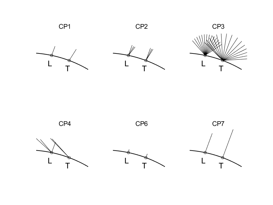
The scan patterns, CP1 – CP7 for each site are shown below the table.
The users can also override the scan patterns with their own scan pattern if they so desire.
| Common Program Scan Patterns | |||||||
|---|---|---|---|---|---|---|---|
| Location* | CP1 | CP2 | CP3 | CP4 | CP5 | CP6 | CP7 |
| UHF | beata | beata | bella | (bella) | – | (manda) | – |
| VHF | (beata) | – | – | bella | – | manda | othia |
| ESR | ipy | tyko | folke | folke | – | manda | othia |
* UHF – Mainland UHF system; VHF – Mainland VHF system; ESR – Svalbard radar
CP Scan Patterns
The mainland system is represented by the trace on the right and the ESR system by the trace on the left.
For example the CP1 is pointing in one single direction, along the local magnetic field direction. The CP2 scan pattern shows that the UHF scans 3 different positions. The ESR uses the 42m field aligned and the moving 32m dish to cover 3 different positions. CP3 is a latitudinal scan, CP4 is low elevation north for polar cap phenomena, CP6 is similar to CP1 but for middle atmospheric phenomena (note that the VHF points vertically), and CP7 is for the topside ionosphere.