


Summary of information related to WP8
The antennas, array layout, receiver front end, and calibration system all play important roles in setting the achievable system performance. The objective of this Work Package is to produce designs of these hardware elements which will be suitable for industrial consideration, and to identify the people who are capable of constructing them.
The results of the earlier work in this area will be revisited, and the results of the FP6 Design Study will either be re-confirmed or updated by taking into account new findings in available hardware, frequency allocation, and user requirements. The outcome of the work package will be devices, subsystems, and systems which fulfil the target performance specifications and are mass-producible.
The activities that will be performed in this Work Package are:
- Specification of the physical and electrical design of the individual antenna elements.
- Identification of possible configurations of the antenna array with respect to the hardware and electromagnetic properties. (The optimisation of the array design for Aperture Synthesis Imaging Radar purposes is determined in WP10).
- Design of the electrical and mechanical front end.
- Investigation of the timing and antenna calibrations.
Deliverables
Deliverable 8.1: Report on the evaluation of possible synchronisation/calibration solutions
October 16, 2012
In the full EISCAT_3D system it is critical that the antenna pattern and phase delay of each element is accurately known at all times.
Deliverable 8.1 presents the results of the evaluation of the synchronization system proposed for EISCAT_3D developed and evaluated by National Instruments, and a number of different calibration options applicable to daily operation of the EISCAT_3D system evaluated by Luleå University of Technology.
The good initial synchronization of the transmitters and receivers used in EISCAT_3D will allow the system to be operated without applying additional calibration. However, non-negligible performance improvements are expected to be achievable by calibrating for not only residual timing errors in the synchronization system, but also for cable delay variations, temperature dependent phase delay of the LNAs, as well as the antenna pattern of individual antennas and their positions. The investigated calibration methods are: celestial radio sources, radar reflections from objects in Earth orbit, local calibration signal injection, global cable-based calibration signal distribution and local calibration towers.
It appears entirely feasible to achieve excellent calibration accuracy using any of the methods presented in this report, but that a combination is required to calibrate both the whole bandwidth of the receiver arrays and the transmitter array. Radar reflections from objects in earth orbit is not only the only method identified so far that can be used to measure full transmitter antenna pattern (including far field phase), but also more efficient than using celestial sources for receiver calibration, but only applicable in the frequency band we are transmitting. Unless accurate antenna models can be used to predict the receiver radiation pattern over the whole bandwidth based on only transmission band measurements, we will also need to perform measurements using celestial radio sources as a complement for the rest of the bandwidth. We do not wish to rule out using local (without the signal distribution network) signal injection as a diagnostic tool for online (receiver antenna) return loss and coupling measurements, but monitoring changes in receiver antenna radiation pattern based on the previous two methods could be sufficient. Similarly, building a limited number of masts in some proximity to the transmitter for probing the field from the transmitting antennas could be useful for measuring variations in phase delay and perhaps a limited number of parameters of a antenna model on shorter time-scales than reflections from objects in orbit around Earth will allow.
Deliverable 8.2: Report on the completed design and testing of the antenna elements and the antenna array
April 8, 2013
Task 8.1 of the EISCAT_3D Preparatory Phase project is considering the design and evaluation of antenna elements.
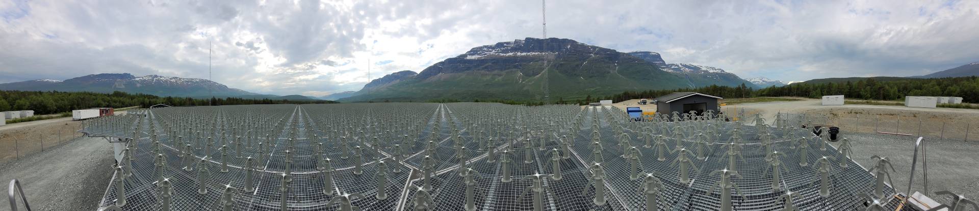
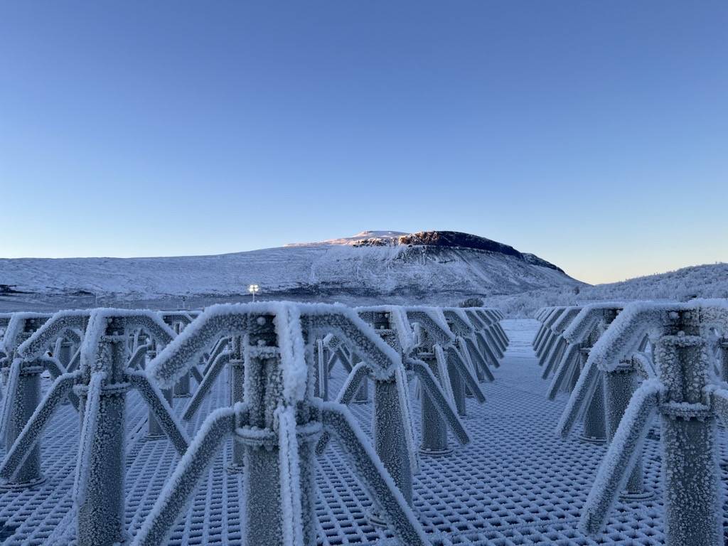
The current version of the performance specification calls for a dual-polarisation antenna that, in an array, shall support transmission over a 5 MHz bandwidth, reception over 30 MHz and steering angles of up to 60 degrees from zenith. The wide steering angle, the modest bandwidth requirements, in combination with requirements on high reliability and mechanical robustness make dipole-based antenna elements attractive for this application. The use of straight or bent dipoles is well established in antenna arrays, examples include the PAVE PAWS and AMISR systems.
This report describes the design method, the resulting antenna and simulation results for this antenna and a reduced array implementation that will be used for verifying the accuracy of the simulated array performance.

The presented antenna fulfills the requirements on the antenna and the antenna array for the EISCAT_3D system. Using the developed simulation automation tools different trade-offs between parameters can easily be found.
Deliverable 8.3: First prototype of the antenna ready
December 6, 2013
Parts of the activities in Work Package 8 of the EISCAT_3D Preparatory Phase project involves design of the antenna elements to be used in the full EISCAT_3D system. Deliverable 8.3 is a report presenting the design of, and measurements on, the first antenna prototype developed in WP8 for the EISCAT_3D system. The work was performed by Gelab AB together with Luleå University of Technology.

Deliverable 8.3 is a report presenting the design of, and measurements on, the first antenna prototype developed in WP8 for the EISCAT_3D system. The work has been performed by Gelab AB together with Luleå University of Technology. The report covers:
- The construction of an electric full-scale model of the “Gunnar Isaksson Antenna no:1”
- Measurements of S-parameters (S11 and S22, Return loss) and radiation pattern of the above constructed full scale model.
Deliverable 8.4: Report on the optimized front-end, including electrical, calibration, mechanical and manufacturing
April 8, 2013
As part of Work Package 8 of the EISCAT_3D Preparatory Phase project a low noise amplifier for the proposed antenna array has been being developed at Luleå University of Technology. The system is expected to operate at approximately 235 MHz with a transmission bandwidth of 5 MHz and a reception bandwidth of 30 MHz. As the sky noise temperature at this frequency range is in the order of 140 K, the aim is for an LNA noise temperature in the order of 30 K. In order to minimise transfer function variations the return loss of the amplifiers should be high (preferably larger than 20 dB).

An LNA subsystem suitable for the EISCAT_3D system was designed and verified, with performance well in line with requirements. As a part of this work a number of low-noise transistors have been characterised for VHF operation and device variation statistics for the most promising device has also been collected.
Deliverable 8.5: Technical report on all WP8 activities
April 8, 2013
This report presents the activities in, and the results from, Work Package (WP) 8 of the EISCAT_3D Preparatory Phase project. This report is written to be read as a stand alone document. Thus, although major parts of activities as well as results have previously been presented in earlier deliverables, this report presents, and in some cases, summarizes them. For more in depth information, references are given to other documents.
This report also covers recent results from the final months of WP8 activities. These recent results are presented in detail, as they are not reported elsewhere.
Milestones
Milestone 8.1: Initial design of the individual antenna elements completed
March 7, 2012
One of the tasks in Work Package 8 of the EISCAT_3D Preparatory Phase project is to specify the physical and electrical design of the individual antenna elements for the system.
The aspects discussed in the first report on these activities are:
- Measurement system capable of measuring the position and time delay of the individual antenna elements.
- The initial design and evaluation of the individual antenna elements.
Based on the findings in this report the following recommendations are made:
- No local measurement system should be built. This option should instead be kept in mind for a future upgrade of the system.
- A folded dipole with a reflector element is the recommended antenna element for the array.
It should be noted that this conclusion is based on having a required bandwidth of 30 MHz; other options must be re-evaluated if this changes. In addition the design presented is an initial design which may change significantly following recommendations from antenna manufacturers.
Further work suggests that the antenna array should be laid out in a triangular grid.
These initial conclusions regarding the design of the antenna elements constitutes Milestone 8.1.
This Milestone was reached in December 2011.
The initial design of the antenna element was then completed in September 2012. The design is published in a technical report, “Design of antenna elements for EISCAT_3D’s phased arrays”, LTU, ISBN 978-91-7439-478-8. This report is available for download from Luleå University of Technology.
Milestone 8.2: Initial specification of the antenna elements and antenna array configuration completed
June 4, 2012
Tasks 8.1 and 8.2 of the EISCAT_3D Preparatory Phase Project concerns specification of the antenna elements and the antenna array configuration. These specifications are collected in a brief report.
The completion of the initial specification of the antenna elements and antenna array configuration is Milestone 8.2.
This Milestone was reached in May 2012.
Milestone 8.3: Performance validation completed for the first front-end prototype
April 9, 2013
Task 8.3 in the EISCAT_3D Preparatory Phase deals with the electric and mechanical front end design.
The performance of the front end prototypes has been evaluated. Complete data for the front end is found in Deliverable 8.4, “Report on the optimized front-end, including electrical, calibration, mechanical and manufacturing”.
This Milestone was reached in September 2013, when the performance of the first front end prototype was evaluated.
Milestone 8.4: The evaluation of possible synchronisation/calibration solutions finished and decided upon
November 26, 2012
The synchronization system proposed for EISCAT_3D, and a number of different calibration options applicable to daily operation of the EISCAT_3D system has been evaluated. The conclusions are available as Deliverable 8.1. This is Milestone 8.4 of the project.
This Milestone was reached in October 2012.
Milestone 8.5: Prototype antenna manufactured
December 6, 2013
The first prototype antenna has been manufactured. The full report on measurements on the antenna is found in Deliverable 8.3, “First prototype of the antenna that will be used in the EISCAT_3D system”.
This Milestone was reached in June 2014.
Attachements
Documents related to WP8 can be found in our external library.