

WP4: Phased array receivers
February 12, 2010
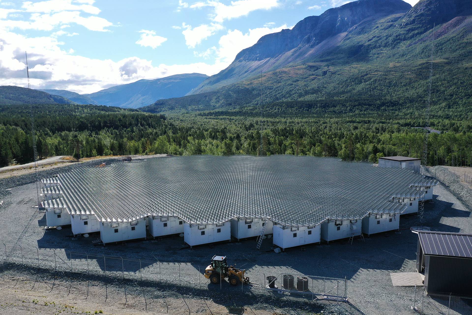
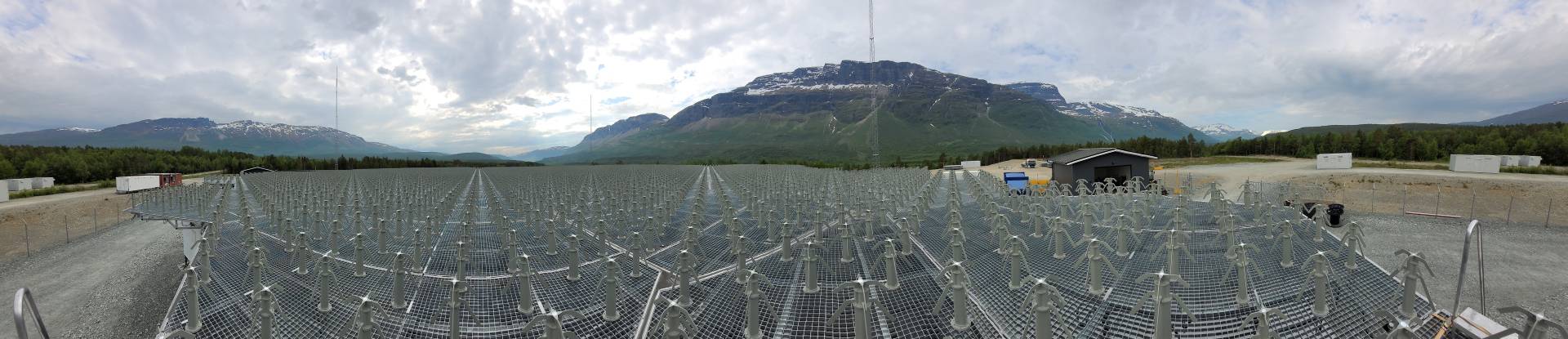
A key element of the EISCAT_3D radar is the ability to receive scattered radar power over a wide range of altitudes by employing an essentially unlimited number of simultaneous receiving beams, generated by sophisticated signal processing of the signals received at the individual antenna elements of two or more large phased arrays located at distances of the order of 100-300 km from the transmitter site. This Work Package was tasked with developing the concept for the receiver and antenna systems capable of realising a multistatic multiple-beam phased array system.
The conclusions from this Work Package can be summarised as follows:
Antenna element
- A simple and flexible antenna array was constructed for the present EISCAT VHF frequency, 224 MHz, using 36 commercially available, high-gain but narrowband off-the-shelf X Yagi antennas as array elements. It was used during the EISCAT_3D Design Study as a test-bed on which to verify both receiver performance as well as a number of other mission-critical concepts.
- The coupling effects between antenna elements in the array influences both receiver array and transmitter array with regard to performance and specifications in the beam forming.
- The interdependence can also be used actively as a means to support and add information to whichever system is used as the main array calibration system. The work on the Element antenna has specifically investigated and simulated the cross coupling effects between two antennas in order to evaluate the possibility to use this in a calibration purpose.
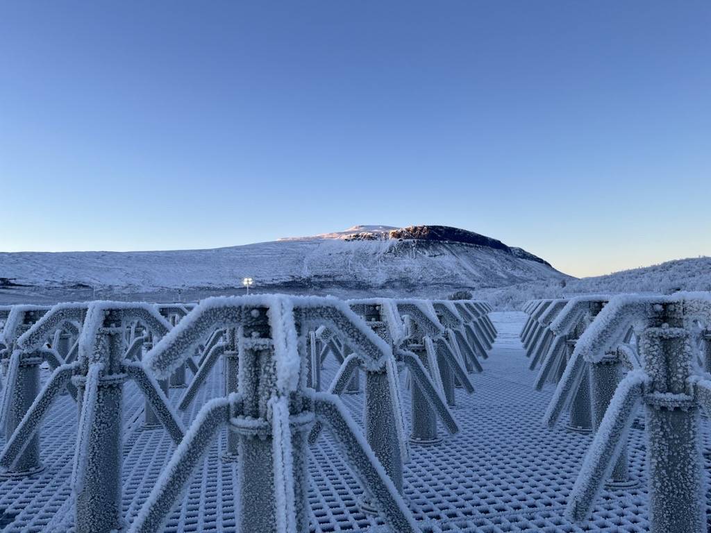
- During snowfall the performance of the antenna is degraded, and under severe conditions the antenna becomes non-operational. To guarantee operability of the system, the effect of snow cover should be taken into account when designing the final antenna.
- Precipitation in the form of snow or rain can also severely degrade the performance of large antenna arrays, in particular if knowledge about the beam shape and pointing direction in absolute numbers is necessary. A method of estimating the far-field of each individual antenna element using the equivalent electric current approach has therefore been developed.
Receiver front end
- Following an initial study, the decision was taken to focus on a solution where commercially available components are used. The main reasons for the decision were performance requirements and the relatively low frequency involved. On chip RF designs are commonly targeting higher frequencies than the EISCAT_3D system. Thus, the implementation of on chip filters and low noise amplifiers in this frequency region would require a substantial effort, with ensuing high risk. Also the requirements on the ADC are reaching available state-of the art, which renders an ASIC implementation insecure. A final consideration in the decision was the desire to keep a flexibility in the deign, which by necessity will be under evolution throughout the development and into a possible implementation phase for the EISCAT_3D system.
- The work on the receiver front end has developed a low noise, under-sampling antenna front end with calibration possibilities in both time and amplitude. The design is centered around two main building blocks: a high performance Low Noise Amplifier (LNA) board with integrated couplers and switches for calibration signal injection, and a 16-bit, 80 Ms ADC board. The system involves active temperature control of the LNA, as well as feedback control of power supply voltages. An extensive control system has been designed to allow remote control and supervision.
Time synchronization
- A crucial constraint in a direct sampled large-area array, like the EISCAT_3D project, is the inter-element timing, which is dictated by requirements on beam pointing accuracy. The beam steering will be performed by Fractional Sample Delay (FSD), which must be able to delay a 30 MHz wide signal band 1/1024th of a sample without introducing phase shifts, and it must all be done in base-band. Also the calibration in regard of amplitude is critical for the performance of the array.
- Two viable solutions to solve the timing distribution have been investigated. The first system is a cable-based system that continuously evaluates the delay between different parts of the timing system, thereby keeping track of any shifts in delay through the system. The second one is based on Global Navigation Satellite Systems (GNSS), which tracks the difference in phase of the signals from satellites to the timing units placed in the center of each sub-array. Both solutions have been evaluated in simulations as well as in measurements. It is shown that they have the capability to match the requirements, but both systems have their strong as well as weak points. Both systems have the capability to perform also calibration of amplitude from each antenna element receiver chain. The cable based system was evaluated in field trials.
- Directly coupled to the timing requirements is also the beam forming algorithms and filters used to achieve these. To evaluate the beam forming performance, and its connection to performance degrading aspects such as noise, jitter, bandwidth, an extensive Matlab simulation system has been designed. The simulation tool models each part of the physical system separately so that parts can be added, updated and removed without affecting the rest of the system. Noise and non-ideal timing performance is included in the simulation. The Matlab simulation tool has allowed the verification and evaluation of the proposed algorithms and timing requirements.
The work in this Work Package was performed by Luleå Technical University.
Deliverable 4.2: EISCAT_3D radar receiver/antenna subsystem report (May 2009)