dlayer.elan
#############################################################################
# dlayer.elan
#
#   EROS3 script for dlayer experiment.
#
#   Versions: 1.00  Unified version for all mainland sites in one elan file
#

############################################################################
# CH1 sampling starts at 60 km and and the last decoded gate is at 126.6 km
# with range res. of 0.6 km
# 0-221 Lags including "faulty" 0 lag, vector length 111 points. This is a D layer pow profile estimate at 80 us lag
# 222-3662 30 Lags 1748 us apart, including "faulty" 0 lag vector length 111 points
# 3663-6437 25 Lags including "faulty" 0 lag, vector length 111 points. This is a D layer lags with 6992 us increment
# 6438-6992 5 Lags including "faulty" 0 lag, vector length 111 points. This is a E layer lag profile with 32 us increment
# 6993-7442 Noise injection from CH 2
# 7443-8192 Backgrouns samples from CH 3
############################################################################

BLOCK dlayer {{scan zenith} {owner CP} {height 292.9}} {

    set scan [string tolower $scan]
    set owner [string toupper $owner]

    set SCAN_PAT $scan 	;# Scan pattern to use (cp1, cp2 or zenith)
    set Owner $owner 	;# Who is running the experiment (CP, SW ... so on)
    set Height $height  ;# Height used in cp1 cp2 and zenith
    #############
    # Definitions
    #############
    set DataDisk "/data"	;# Where should data go
    set XDIR /kst/exp/dlayer	;# Default directory
    set Version 1.00		;# What version
    set FIR /kst/dsp/fir	;# Where we have fir filters
    set Expname  "dlayer"         ;# experiment name
    set Iper_us  4900000	;# Integration time in us
    set LOOPC 28		;# loops for one integration
    set SYNC 56000		;# sync time between integrations
    set SCAN_FILE "/kst/exp/scans/scanpatterns.elan" ;# Where we have scan file

    # On what radar are we
    if {[ISUHF]} {
        set RADAR uhf
        set Site "u
	}
    if {[ISVHF]} {
        set Site "v
        set RADAR vhf
	}


    # Filter to use
    if {[ISUHF]} {
        set Filter123 $FIR/b150d60.fir     ;# +-150 kHz filter for 4 usec sampling
    }
    if {[ISVHF]} {
        set Filter123 $FIR/b150d60.fir     ;# +-150 kHz filter for 4 usec sampling
    }

    # NCO file to load into channels boards
    set NCO1 $XDIR/ch1_${Expname}-${Site}.nco
    set NCO2 $XDIR/ch2_${Expname}-${Site}.nco
    set NCO3 $XDIR/ch2_${Expname}-${Site}.nco
    # DSP file to use
	set Corrfile $XDIR/${Expname}-${Site}.fil

        set Expfiles [list $XDIR/$Expname.elan $SCAN_FILE $Corrfile \
        $XDIR/${Expname}-$Site.tlan $XDIR/rtg_def.m \
        $NCO1 $NCO2 $NCO3  $Filter123 ]

# Make Experiment ID
    set Expid    "kst0 ${Expname}${Site}_${SCAN_PAT}_${Version}_${Owner}"

    #############
    # Actual work
    #############
    # Get all different scan patterns
    source ${SCAN_FILE}

    # Stop receiver --

    SYNC -10

    stopradar -rec
    if {[ISUHF]||[ISVHF]} {
   	 stopradar -trans
	}
    stopdata

     # Load radar controller --

     loadradar rec -loopc ${LOOPC} -sync ${SYNC} -file $XDIR/${Expname}-${Site}_${RADAR}.rbin  -prog1 0

    if {[ISUHF]||[ISVHF]} {
   	mount $DataDisk ;# mount the desired data disk
	loadradar trans -loopc ${LOOPC} -sync ${SYNC} -file $XDIR/${Expname}-${Site}_${RADAR}.tbin -prog1 0
	}


    # Load filters --

    loadfilter $Filter123 ch1,2,3

    # Set frequencies --

    loadfrequency $NCO1 ch1
    loadfrequency $NCO2 ch2
    loadfrequency $NCO3 ch3


    setfrequency ch1, ch2, ch3  12.0

    # Start radar controllers --

    SYNC 2
    armradar rec -prog1
    if {[ISUHF]||[ISVHF]} {
	armradar trans -prog1
	}

    startradar EXPSTART [expr double($Iper_us)/double(1000000)]

    # Start data access ---------------------------------------------------------

    SYNC 4

    startdata $Corrfile $Expid $Iper_us
    writeexperimentfile $Expfiles


    SYNC 4
    disablerecording

    # Infinite scanning loop

    set ExpStart [timestamp [getstarttime exp]]
    gotoblock  ${SCAN_PAT} $ExpStart $Expname $Height

    # Ensure that we will not fall out of this proc

    DO -1 { SYNC 100 }

};#dlayer
eval callblock dlayer [argv]
fir_decoder.txt
In the dlayer and the sideloob free arc experiments, a number of different
codes sets are transmitted. These codes are decoded and different
lag products are formed.
dlayer experiment:
100 different 40 Baud codes are transmitted. In each code cycle, 150
samples are taken. All of these samples are stored for one whole code
sequence. From these data long inter pulse lags can be formed, also
short lags with data coming from one code can also be calculated. The
long inter pulse lags are calculated like this: From each code cycle
the corresponding data are FIR decoded with the the transmitted code. In
the dlayer experiment a window function is applied to the FIR decoding
values. After the decoder each IPP data will be 111 samples long.
Note that the used FIR taps are normalized, this is done by summing up
all FIR taps and divide this value with all individual FIR taps.
Memory map:
cycle 1 | 2 | 3 | 4 | ...... | 100 |
samples |...111...|...111...|..111..|...111...|........|...111...|
time us 0 1748 2*1748 3*1748 4*1748 100*1748
To calculate interpulse lags the lag_incr variable is used, this sets how many
lags/samples that should be jumped over after each calculated lag. In
this case it is set to lag_incr=111; we will only calculate the wanted
IPP lags. In the dlayer experiment we calculate 34 1748 us lags, this
giving max_lag=3330;
After the lag profiling we will have lag matrix like this:
100 contributions to lag 0
99 contributions to lag 1
98 contributions to lag 2
.
.
67 contributions to lag 33
Each lag profile can be integrated so we end up with a lag profile
containing lag0 lag1 lag2 ... lag33 each of them 111 samples long.
Due to limited computational power in the crate computer (CPU50T) we can
not compute all possible lags, to be able to calculate lag out to ~0.17 s
we need to use coherent sub integration of IPPs. In the current dlayer
experiments we coherently integrate 4 FIR decoded IPPs (sub_int=4;)
Note sub_int must be divisible with the number of codes.
cycle 1 |...111...|cycle 5 |...111...| ..... cycle 97 |...111...|
+ + +
cycle 2 |...111...|cycle 6 |...111...| ..... cycle 98 |...111...|
+ + +
cycle 3 |...111...|cycle 7 |...111...| ..... cycle 99 |...111...|
+ + +
cycle 4 |...111...|cycle 8 |...111...| ..... cycle 100 |...111...|
|...111...| |...111...| ..... |...111...|
cycle 1 cycle 2 cycle 25
Cycle 1 will be at 0 us, cycle 2 at 4*1748=6992 us, cycle 25 at
24*4*1748=167808 us. After that the lag profile are calculated with
a lag_incr of 111, max_lag=2664; which is 24*111.
For the short lags which is formed inside a IPP a similar approach is
taken. In the dlayer experiment the sample speed is 4 us. To calculate
a 80 us lag we need 20 samples.
These "lags" can be formed using a decoding filter like this:
Sub code 1_1 1_2 2_1 2_2 3_1 3_2 4_1 4_2 100_1 100_2
|.20.|.20.| |.20.|.20.| |.20.|.20.| |.20.|.20.| .. |.20.|.20.|
Code 1 2 3 4 .. 100
Code is the transmitted code and the Sub code is the code which will be
used to decode each IPP. Each IPP will be decoded first with the Sub
code n_1 and than sub code n_2. First sub code will decode starting at
sample zero up to sample 130 the next sub_code goes decodes sample from
20 up to sample 150 in this case. After this decoding process for each
IPP the memory will look like this.
cycle 1_1 1_2 | 2_1 2_2 | | 100_1 100_2 |
samples |..111..|..111..|..111..|..111..|.............|..111..|..111..|
time us 0 80 1748 1828 99*1748 99*1748+80
We will calculate max_lag=111; and lag_incr=111; it will look like this
for the 80 us lag:
cycle 1_1 1_2 | 2_1 2_2 | 3_1 100_1 100_2 |
samples |..111..|..111..|..111..|..111..|..111..|.....|..111..|..111..|
cycle 1_1 1_2 | 2_1 2_2 | 99_2 | 100_1
samples |..111..|..111..|..111..|..111..|.....|..111..|..111..|
Lag at: 80 us 1668 us 80 us 1668 us 80 us 1668 us
lag 0 1_1*1_1 1_2*1_2 2_1*2_1 2_2*2_2 3_1*3_1 3_2*3_2 4_1*4_1 4_2*4_2 ....
lag 1 1_2*1_1 2_1*1_2 2_2*2_1 3_1*2_2 3_2*3_1 4_1*3_2 4_2*4_1 5_1*4_2 ....
From this we can see that we will have inter pulse lags like 2_1*1_2
3_1*2_2 and so on. These will be automatically removed when the data
are integrated. The integration is made in the same way as for
the inter pulse lags.
For the E layer the lags are calculated in the same manner. Here the
FIR decode file is divided in five pieces nr_fir_passes=5; so the lag
resolution will be 40/5*4=32 us max_lag=444; and lag_incr=111;
LAG 1 at 32 us
cycle 1_1 1_2 1_3 1_4 | 2_1 2_2
samples |...111...|...111...|...111...|...111...|...3_1...|...111...|
cycle 1_1 1_2 1_3 1_4 | 2_1
samples |...111...|...111...|...111...|...111...|...111...|
Lag at: 32 us 32 us 32 us 1716 us 32 us
lag 0 1_1*1_1 1_2*1_2 1_3*1_3 1_4*1_4 2_1*2_1 2_2*2_2 2_3*2_3 2_4*2_4 ....
lag 1 1_2*1_1 1_3*1_2 1_4*1_3 2_1*1_4 2_2*2_1 2_3*2_2 2_4*2_3 3_1*2_4 ....
lag 2 1_3*1_1 1_4*1_2 2_1*1_3 2_2*1_4 2_3*2_1 2_4*2_2 3_1*2_3 3_2*2_4 ....
lag 3 1_4*1_1 2_1*1_2 2_2*1_3 2_3*1_4 2_4*2_1 3_1*2_2 3_2*2_3 3_3*2_4 ....
Also here we will have inter pulse lags 2_1*1_4 3_1*2_4 and so on for
the first lag (32 us). For lag 2 (64 us) the
inter pulse lags will be 2_1*1_3 2_2*1_4 and so on, these will
be removed during integration.
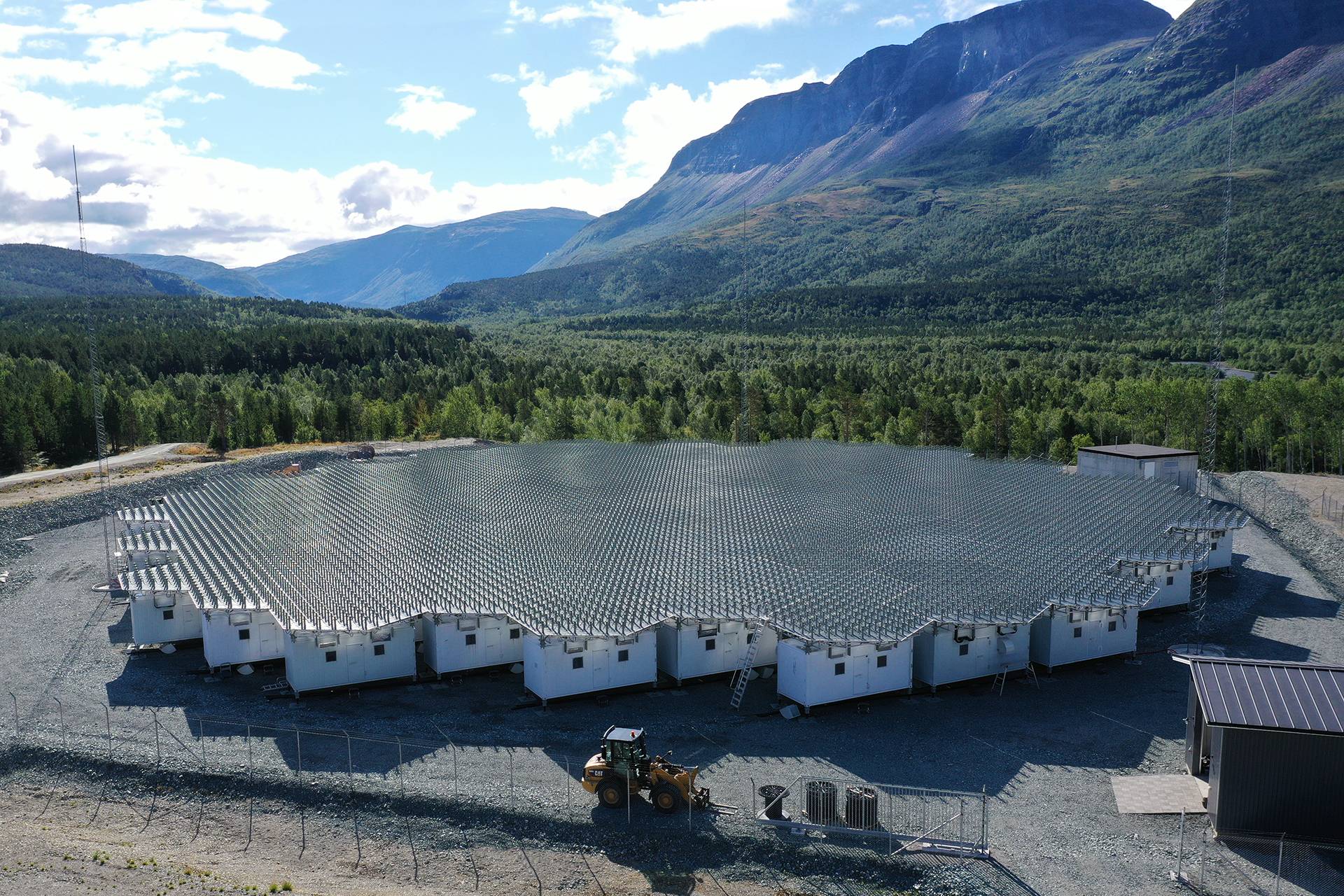
At ESR (Svalbard) a simple ground clutter removal algorithm have been used,
the whole code cycle is transmitted twice, and these two code cycles are
subtracted from each other in amplitude domain. This will acts as notch filter
at 1/(100*IPP) Hz in frequency domain (current dlayer experiement have an IPP
of 1748e-6 s), and thus remove strong coherent echoes from the surrounding
mountains at ranges around 100 km.
calc_const.m
%This script need to be run from the same dir where the used fir decoder files are
load code1.txt  % Load decode set for 1748 us lags
load code2.txt  % Load decode set for 80 us lag
load code3.txt  % Load decoder set for 4*1748 us lags
loops=100;      % Nr of code set
nr_codes=40;    % Nr of bit in each code set
sub_ints=4;     % Nr of coherent integration in long lags
max_lag_e=4;    % max lag for E layer part
win_len=nr_codes;
%Calculate used window function for 1748 us decoder
wind_full=sqrt(sqrt(cos((1:win_len)*pi/(win_len)-pi/2-pi/(2*win_len))));
win_len=nr_codes/2;
%Calculate used window function for 80 us decoder
wind_half=sqrt(sqrt(cos((1:win_len)*pi/(win_len)-pi/2-pi/(2*win_len))));
win_len=nr_codes/5;
%Calculate used window function for 4*1748 us decoder
wind_8=sqrt(sqrt(cos((1:win_len)*pi/(win_len)-pi/2-pi/(2*win_len))));
const1=(((loops-1)*(sum(wind_full)/sum(code1)).^2)/(loops*((sum(wind_half)/sum(code2)).^2)));
const2=(((loops-1)*(sum(wind_full)/sum(code1)).^2)/(loops*max_lag_e*((sum(wind_8)/sum(code3)).^2)));
const3=((sub_ints*(loops-sub_ints)*(sum(wind_full)/sum(code1)).^2)/(loops*((sum(wind_half)/sum(code2)).
^2)));
const4=((sub_ints*(loops-sub_ints)*(sum(wind_full)/sum(code1)).^2)/(loops*max_lag_e*((sum(wind_8)/sum(c
ode3)).^2)));
% Calculate the ratio between the different type of lags
sprintf('ratio between 1748 us lag and 80 us is %5.3f\n',const1)
sprintf('ratio between 1748 us lag and 32 us is %5.3f\n',const2)
sprintf('ratio between 4*1748 us lag and 80 us is %5.3f\n',const3)
sprintf('ratio between 4*1748 us lag and 32 us is %5.3f\n',const4)
spectra.m
%This example requires a allready loaded matlab file
% Take out the 1.75 ms lags
lags=d_data(222+111:3662);
% Take out the 4*1.75 ms lags
lagl=d_data(3663+111:6437);
% Take out the 80 us lag
lag_80=d_data(111:111+110);
% Take out the 32 us lag
lag_32=d_data(6438+111:6438+111+110);
% Set together the 80 us lag and the 1.75 ms lags and also normalize data
acfs=[9.551.*lag_80 reshape(lags,111,30)].*(1./((ones(111,1)*(100/100:-1/100:70/100))));
% Set together the 80 us lag and the 4*1.75 ms lags and also normalize data
acfl=[37.048.*lag_80 reshape(lagl,111,24)].*(1./((ones(111,1)*(25/25:-1/25:1/25))));
% Set together the 32 us lag and the 1.75 ms lags and also normalize data
acfs_32=[10.408.*lag_32 reshape(lags,111,30)].*(1./((ones(111,1)*(100/100:-1/100:70/100))));
% Set together the 32 us lag and the 4*1.75 ms lags and also normalize data
acfl_32=[40.371.*lag_32 reshape(lagl,111,24)].*(1./((ones(111,1)*(25/25:-1/25:1/25))));
% For example take out the lag 0 data from the 80 us + 4*1.75 ms data
lag0=acfl_32(:,1);
dlayer-v.fil
% This is the ordinary singel beam dlayer experiment for the VHF radar

% Only one STC in the tarlan file
nr_stc=1;
% Channel one
% Channel board one is the signal carrying channel
channel=1;
% We are starting with D layer power profile estimate at 80 us
% using the type four which is the fir pulse to pulse decoder.
type=4;
% in this experiment we are transmitting 100 different 40 Bauds codes
% after each other, samples from each IPP is stored for further decoding
% We will do 100 subcycles
% In each IPP we will take 150 samples as we have 100 codes we will
% take a total of 150*100=15000 samples
	vec_len=15000;
% The sub_vec_len label tells of many samples we have taken in each IPP
	sub_vec_len=150;
% Each subcycle will have 20 baud code
	fir_len=20;
% The file containing the code used for decoding
% This file have each code element on a single row so this file will
% be 100*40=4000 lines long. This file can have floating point values
% or inetegers. In this file for the particular experiment an
% window function is applied to the code file.
% PLEASE note the fir decoding file should be reversed
% for example you transmit 1, -1, -1, 1, 1
% decoding file will be    1, 1, -1, -1, 1
	fir_file=code2.txt;
% Do 1 lag 80 us apart
% To understand the decoding algorithm please see fir_decoder.txt
% This file also contain information on the rest of the labels used here
	max_lag=111; % Number of lags will be (max_lag/lag_incr)
	lag_incr=111; % lag_incr is sub_vec_len-fir_len+1-(fir_passes-1)*code_len
	nr_fir_passes=2;
	data_start=0;
end_type
%% Dlayer long lags
type=4;
% We will do 100 subcycles
	vec_len=15000;
	sub_vec_len=150;
% Each subcycle will have 40 baud code
	fir_len=40;
	fir_file=code1.txt;
	data_start=0;
	fir_res_save=1;	% Save the fir:ed data for use in the next type
% Do 30 lags 1.75 ms apart
	max_lag=3330; % Number of lags will be max_lag/lag_incr
	lag_incr=111; % lag_incr is sub_vec_len-fir_len+1
end_type
%% Dlayer long lags with higher frequency resoulution
type=4;
% We will do 100 subcycles
	vec_len=15000;
	sub_vec_len=150;
% Each subcycle will have 40 baud code
	fir_len=40;
	fir_file=code1.txt;
	sub_int=4;
	data_start=0;
	fir_res_use=1;	%Use the fir:ed data from the type before
% Do 24 lags 6.99 ms apart
	max_lag=2664; % Number of lags will be max_lag/lag_incr
	lag_incr=111; % lag_incr is sub_vec_len-fir_len+1
end_type
%% Short 32 us lags for the E region
type=4;
% We will do 100 subcycles
	vec_len=15000;
	sub_vec_len=150;
% Each subcycle will have 8 baud code
	fir_len=8;
	fir_file=code3.txt;
	nr_fir_passes=5;
	data_start=0;
% Do 4 lags 32 us apart
	max_lag=444;  % Number of lags will be (max_lag/lag_incr)
	lag_incr=111; % lag_incr is sub_vec_len-fir_len+1-(fir_passes-1)*code_len
end_type
end_chan
% Channel two
% Calibration channel
channel=2;
type=1;
	vec_len=750;
	max_lag=0;
	data_start=0;
end_type
end_chan
% Background channel
channel=3;
type=1;
	vec_len=750;
	max_lag=0;
	data_start=0;
end_type
end_chan
dlayer-v.DECO
DECO 2.0
1	650739
8493
6
% Channel=1 type=4 data_start=0 vec_len=15000 max_lag=111 res_mult=1 sub_div=1 do_zlag=0 lag_incr=111 fir_len=20
% Data position 0 - 221
1	J	1	0	44289	0	1	1	0	111	0	0	222	0	6	 100 2 1 222 111 20 /kst/exp/dlayer-v/code2.txt
% Channel=1 type=4 data_start=0 vec_len=15000 max_lag=3330 res_mult=1 sub_div=1 do_zlag=0 lag_incr=111 fir_len=40
% Data position 222 - 3662
2	J	1	44289	292485	0	30	1	0	111	0	222	3441	0	6	 100 1 1 3441 111 40 /kst/exp/dlayer-v/code1.txt
% Channel=1 type=4 data_start=0 vec_len=15000 max_lag=2664 res_mult=1 sub_div=1 do_zlag=0 lag_incr=111 fir_len=40
% Data position 3663 - 6437
3	J	1	336774	36075	0	24	1	0	111	0	3663	2775	0	6	 25 1 1 2775 111 40 /kst/exp/dlayer-v/code1.txt
% Channel=1 type=4 data_start=0 vec_len=15000 max_lag=444 res_mult=1 sub_div=1 do_zlag=0 lag_incr=111 fir_len=8
% Data position 6438 - 6992
4	J	1	372849	276390	0	4	1	0	111	0	6438	555	0	6	 100 5 1 555 111 8 /kst/exp/dlayer-v/code3.txt
% Channel=2 type=1 data_start=0 vec_len=750 max_lag=0 res_mult=1 sub_div=1 do_zlag=0 lag_incr=1 fir_len=0
% Data position 6993 - 7742
5	G	1	649239	750	0	0	1	0	750	0	6993	750	0	0
% Channel=3 type=1 data_start=0 vec_len=750 max_lag=0 res_mult=1 sub_div=1 do_zlag=0 lag_incr=1 fir_len=0
% Data position 7743 - 8492
6	G	1	649989	750	0	0	1	0	750	0	7743	750	0	0
ch1_dlayer-v.nco
NCOPAR_VS       0.1
%======================================
% ch1_dlay
% LO1=298.0 MHz LO2=84.0 MHz
%======================================
NCO     1        10.0   % f8