

Tender 1: Antenna Unit [CLOSED]
Status: 2018-03-26 Contract Signed
Selected Vendor
EISCAT has signed a contract for the delivery of the Antenna Unit for EISCAT_3D with ECRIEE (East China Research Institute of Electronic Engineering).
ECRIEE, established in 1965, is a leading radar producer worldwide. It is a major member of CETC (China Electronics Technology Group Corporation) which is the Number 1 IT technology company in China and is in the list of Fortune Global 500. Headquartered in Hefei city, China, ECRIEE currently has 3 800 employees and reported sales of CNY/RMB 4.98 billion in 2017 (source: ECRIEE, 2018-03-26).
Published documents

Call for expression of interest for e3ds1 AU
Technical specification for e3ds1 AU (updated)
Deadline for EOI replies: CALL CLOSED
Questions and Answers
Last update: 2018-01-26
Question 1: How do we express our interest to participate in the Antenna Unit (E3DS1 AU) tendering?
Answer 1:
- For the AU, please first consider the scope of the tender:
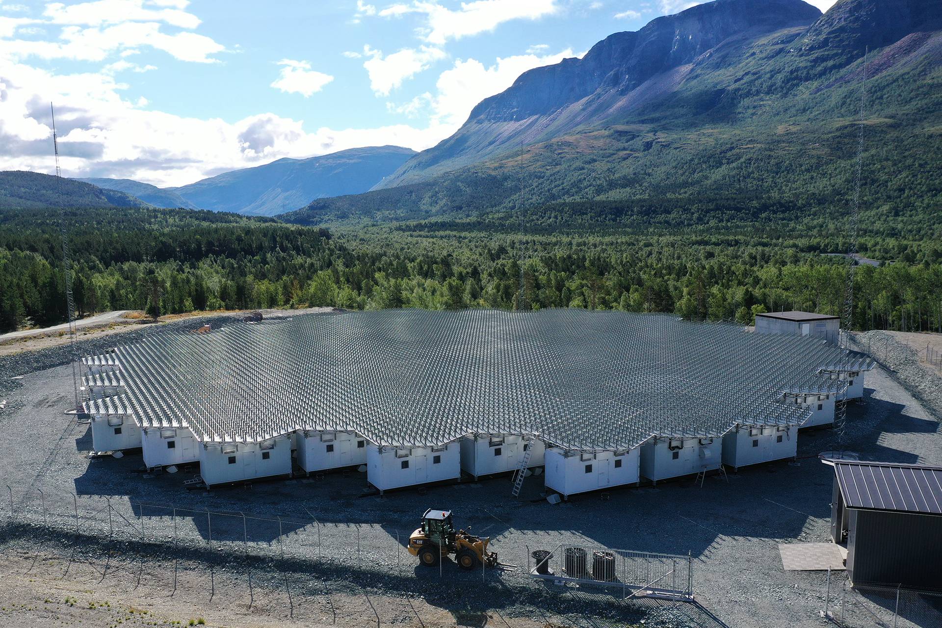
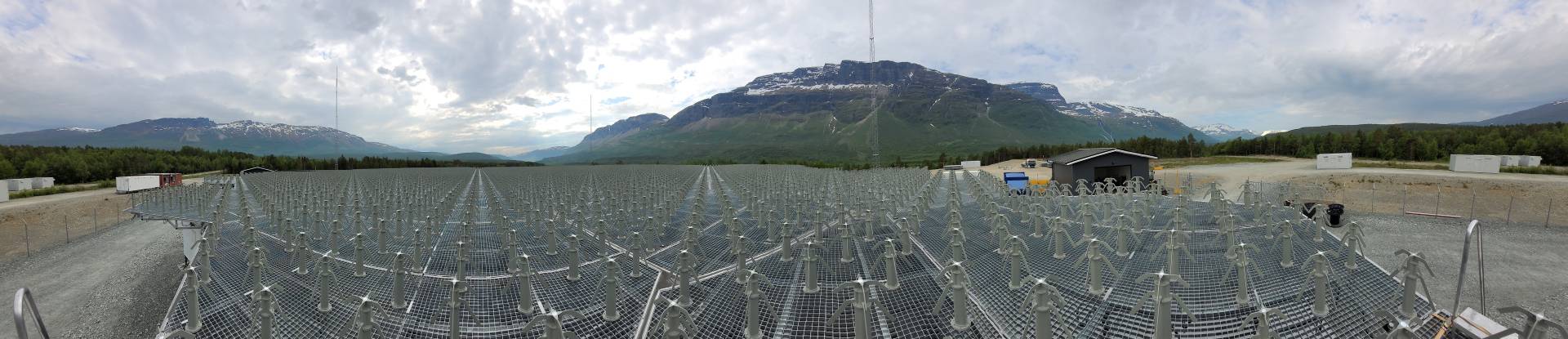
- Minimally 3 arrays with ~5 000 – ~10 000 antenna elements to be installed in Finland, Norway and Sweden + options (paragraph 4). The system details are included in the preliminary technical specifications. For the expression of interest, you do not need to reply to the technical requirements. Please just confirm that your firm is capable of designing and delivering such systems (and that you have done similar works before – paragraph 10)
- Then consider the overall concept of the process, including delivery times and locations and suggested contract details.
- Finally, please reply to the Tender qualification requirements given in the first part of the call (paragraph 10)
- The reply format is given in paragraph 13.
- Example: 1 – noted, 2 – noted, 3 – accepted…
- Signed by…
Question 2: When will we know the outcome of our reply to the Expression of Interest relating to the ED3S1 AU?
Answer 2: We aim to send out the tendering packages to the invited Tenderers around 3 January 2018
Question 3: Will there be other EISCAT_3D business opportunities coming soon?
Answer 3: We plan to advertise calls relating to site buildings, site construction works, and analogue and digital receivers, etc. within the coming few months. The calls will be posted here (eiscat.se/business/tenders) and, when relevant, on TED (Tenders Electronic Daily – the online version of the ‘Supplement to the Official Journal’ of the EU)
E3DS1 AU Dialogue phase
Started 2018-01-03
Question 4: Is EISCAT expecting tenders only to produce the antenna element and array structure designed in the EISCAT_3D_PfP phase or to design a new antenna unit?
Answer 4: We have indeed our own design for the antenna elements and structures, however, results from tests are not good enough to be the final product. We are asking tenders to optimize the design and make it mass producible. So answer is that reference structure can be used as a start but we like to see a better design from the selected tender.
Question 5: Do we need to resend already given information like CVs and company information?
Answer 5: Items which are already explained in the expression of interest documents are not needed to repeat. Just mark as a ‘Fulfilled’.
Question 6: A question about “App4_Requirements_Answer_Template_for_AU ver1-0”, Chapter 1.1. What does “Positions” mean? Is it a physical location or position of deliverable or milestone of project?
Answer 6: Position here means delivery item.
Question 7: What means ‘Flat response’ in the SS_AU_02_06 and SS_AU_03_12.
Answer 7: ‘Flat response’ in the SS_AU_02_06 and SS_AU_03_12 means that in all directions inside the scan area (+- 60 deg from zenith, 360 deg azimuth) the antenna array gain should be equal.
Question 8: In the requirement “SS_AU_03_16”? “Antenna Elements and Array shall be optimized to have better than – 20 dB mutual coupling. How you define mutual coupling?
Answer 8: Mutual coupling is S21 measurement between two nearest antennas. In the test array we have measured -15 dB coupling from one antenna to other and when adding all together in worst case we have measured almost the same forward power than return power. This needs some adjustment in the antenna parameters. We expect that final antenna configuration will be made during the design phase of the project.
Question 9: Would you please confirm the following within the check list section 2:
- Evidence of Safety Management System according to SOW 40. Should read “to SOW 36”
- Evidence of Environmental Management System according to SOW 46. Should read “to SOW 42”
Answer 9: Yes, we can confirm that check list in the Section 2 of App4_Requirements_Answer_Template_for_AU_ver1-0.docx ther are two mistakes. Correct ones are:
- Evidence of Safety Management System according to SOW 36.
- Evidence of Environmental Management System according to SOW 42.
Question 10: In the previous project (EISCAT3D_pfp) antenna array was referring to 91 antennas (SS_AU_36: gain 25 dBi) and in the new requirement (SS_AU_03_12: gain 45 dBi) is refering to array of 9919 antennas. Is that correct?
Answer 10: Yes, it is correct. Term Array structure refers to the whole array of about 10 000 antennas. Sub-array term is used for 91 antennas connected to the amplifiers and receivers in the same sub-array container. We like to point out that, although all antennas in the array should be placed in a hexagonal form, sub-array structure under antennas does not need to be.
Question 11: What is expected to deliver 2018-01-19?
Answer 11: We have new instructions concerning this and we regret for any inconveniences.
We do not expect any delivery at that time. Tenders should go through all technical requirements and request clarifications and changes if needed. We will then send updated documents, if needed, which will include clarifications and changes agreed during the dialogue period. Such alterations will be clearly marked in the updated tendering documents.
Question 12: What is the length requirement for the cable from antenna element to the container?
Answer 12: It is up to supplier to design the cabling to be as short as possible to minimize the signal loss. The EISCAT3D_PfP test array the cable length was 9 meters and we have estimated that 7 meter cables may have been possible with that AU design. The antenna cables must support two configurations: one with Transmit Units (TUs) installed in evenly in the container and one with only First Stage Receive Units (FSRUs) installed.
Question 13: One more question about “Flat Response”, you have replied that the antenna array gain should be equal, actually there will be a slight drop of gain when the beam scans from zenith to 60degree. So, if this requirement means the antenna array gain of 60 degree is also >45dBi, and the gain curve must be smooth? Is the antenna array gain (>45 dBi) tested on full frequency band (218MHz~248MHz) or on a critical frequency, and contains what losses (such as whether or not the cable loss is included)?
Answer 13: Exact numbers shall be optimized during the design phase. The important point is that all look directions down to 60-degree zenith angles are equally important and that the design should not be optimized for the zenith direction alone. We recognize that the gain will decrease with zenith angle and that it may be 3 dB down at the maximum scan angles due to geometric effects. The goal is to have a gain better than 45 dBi in the zenith direction and minimal reduction for scan directions down to 60 degree zenith angle. At the same time, we do want gain reduction at very large zenith angles (near 90 degrees) to aid in the rejection of interfering signals produced on the ground. Cable losses should be minimized so they have negligible impact on the overall antenna gain and added noise figure.
Question 14: One more question about “Mutual Coupling better than -20dB”, may I know the reason for setting this value? According to our understanding, the mutual coupling and active return loss of antenna array are related, if we can realize the antenna array active return loss >15dB, is it still necessary to achieve mutual coupling better than 20dB?
Answer 14: Correct. Our absolute limit is an active reflection better than -10dB in all scan directions, so -15 dB is very good. Using -20 dB mutual coupling we should come to close to the same return power.
Question 15: About CE marking requirements, because the final deliverable is a custom item, do you have more detailed requirement? Are all the parts of deliverable need to have CE marking?
Answer 15: For this procurement CE marking is not needed.
Question 16: Can we understand “ss_au_03_13” as the sidelobe of 90 degree <-15dB?
Answer 16: This is meant to be a guidance value for antenna element and array design. The goal is to have a gain better than 45 dBi in the zenith and greater than 42 dBi on all scan directions down to 60 degree zenith angle. At the same time, we wish to have very little gain near the horizon where terrestrial interference sources are located.
Question 17: How about the electromagnetic shielding level of the container?
Answer 17: A good electromagnetic isolation between the radiating antennas and the electronics in the container is required. This can be provided via a combination of shielding of the container together with the effect of the ground plain. Attenuation from inside container to the antenna elements over the receiving band (233 +- 15 MHz ) should be more than 100 dB.
Question 18: We note that there are two “SS_AU_01_04” items, one pertaining to signal loss and another to the project plan. We request that EISCAT clarifies what is meant by the “project plan” section.
Answer 18: Correct, there is an error on numbering. SS_AU_01_06 Project plan is one delivery item after design phase.
Question 19: SS_AU_02_06. The elevation scan pattern is required to have a flat response. It is not clear what the tolerance is on the flatness of that response (c.f. SS_AU_03_12, _13 and _15). We request that EISCAT clarifies the requirements regarding antenna response.
Answer 19: Parameters for antenna scan pattern are part of the design phase optimization work. The goal is to have a gain better than 45 dBi in the zenith and greater than 42 dBi on all scan directions down to 60 degree zenith angle. At the same time, we wish to have very little gain near the horizon where terrestrial interference sources are located.
Question 20: SS_AU_02_09. We assume that 50 ohms is an antenna-array centre impedance. A requirement of 50 ohms at the array edge will place additional constraint on the design (in terms of ground plane area and dummy load coupling).
Answer 20: For transmission purpose we expect that all antennas have a good return loss value. Antennas located on the outer ring can have reduced performance, but -10 dB return loss is still expected.
Question 21: SS_AU_03_10, SS_AU_03_11. We note the required approximate size of 80m, and EISCAT’s provided concept drawing of 75m. We believe that to meet the requirements of SS_AU_03_13 and _15, the physics will require are larger area. We would like EISCAT to clarify if there are hard requirements pertaining to antenna array unit size, and priority between this and the RF requirements.
Answer 21: Mutual coupling is very important parameter and slight changes to the array size is allowed. We have hard limit for 100 m diameter circular area including fence but in extreme case if needed the number of antennas in the array can be smaller.
Question 22: SS_AU_03_16. We noted that this requirement was present in the “App4_Requiements_Answer_Template_for_AU_ver1-0”, but there was no equivalent requirement in the technical specification document. If there is an additional, requirement, we request that EISCAT provide this for us.
Answer 22: That is an error in the file ‘App4_Requiements_Answer_Template_for_AU_ver1-0’. No requirement SS_AU_03_16 exists for the moment.
Question 23: SOW 12. External design and manufacture will be on premises provided by the Contractor, and will not require design or production facilities from EISCAT. However, as a result of the installation work, deployment will necessitate the delivery and on-site installation and commissioning of the delivered systems. Although this is not a financial charge made to EISCAT, it is a necessary cooperation with the EISCAT facility and the use of the site resources as appropriate. We note that EISCAT has indicated that a separate document is to be provided (EISCAT Supplied Resources, SOW 17). We therefore assume that SOW 12 means that no additional requirements will be made beyond what is specified in response to SOW 17.
Answer 23: Correct. Resources required from EISCAT shall be specified in the document included in the quotation. It should be mention that sites (Skibotn, Karesuvanto and Kaisaniemi) are empty without any resources available. EISCAT will prepare the ground as mentioned in the tendering documents. Also access roads and electricity will be prepared. Electricity can be used without extra costs.
Question 24: SOW 54. Our understanding of SOW 54 is that the First Article (91-antenna unit) will be verified before series production – and not series production verification – commences. That is, we shall not start the series production itself until the First Article has passed the verification test. We would like to receive clarification from EISCAT that this is what they intend by SOW 54.
Answer 24: Correct. First Article is to verify that system is as expected and also verify integration to other units. At the Production Reediness Review acceptance for production is given.
Question 25: SOW 63. We assume that verification tests will be carried out by EISCAT staff, with assistance of supplier staff. We assume that EISCAT staff will be considered independent for the purposes of the verification tests. We would like EISCAT to confirm that this is there intention, or whether an independent 3rd party needs to be employed to conduct the complete verification process.
Answer 25: EISCAT personnel or resources contracted by EISCAT will be used for the verification process.
Question 26: SS_AU_04_04. The solution we anticipate will not reach 20 kW, both from a production and operational point-of-view. This applies particularly to the receiver system. We would like to know if EISCAT intend to include additional equipment in the enclosures, which would require contingency on our part, or whether the system can be completely optimized for cost-efficient operation.
Answer 26: Our amplifier supplier has design which takes about 6 racks for 182 units. In addition to that we have estimated half rack for receiver and half rack for computer and timing systems. 20 kW thermal power is an estimation using very modest efficiency value. Design for amplifier unit is already fixed and it includes also TR-switches and isolators. Those have to be inside cabin and installed to the racks.
Question 27: SOW 33 and SOW 14. We note that we make use of trusted partners to acts as subcontractors for production of required items. We do not necessarily have access to the internal working process of those subcontractors, without negotiation. We therefore assume that the EISCAT interaction is a right to monitor work at the primary contractor premises and that participation will be at cooperative involvement. We would like to received clarification from EISCAT to what degree they would anticipate
participating in the work. (An example would assist in our understanding of their expected involvement).
Answer 27: EISCAT needs to understand and follow the manufacturing so that the quality of product can be estimated. An NDA between supplier and EISCAT can be signed. Details shall be agreed during contract negotiation phase.
Question 27: The interface to ground is the gravel bed. There will also be electrical and fibre distribution in/on the gravel bed. This means that the antenna structure may be blocked by other installations on ground. If that happens, whose responsibility is it to relocate either parts of the antenna structure, or the other installations?
Answer 27: The actual footprint of the antenna structure will be mutually agreed during the final design of the antenna unit. That includes also how the electrical and fibre installations will distributed to each of the containers.
E3DS1 AU Dialogue phase
Ended 2018-01-19
Question 28: Utilizing 6 racks to hold amplifiers, what will the mechanical load/rack be of the amplifier/TXRX switch units. Or weight/unit and how many units/rack.
Answer 28: Amplifiers for one rack will weight around 200 Kg and instruments for the 7th rack around 100 Kg.
Question 29: Will the solution be built in such a way that it is possible to mount a standard 5 pole 3*16A outlet at each rack, and then sub distribution to the each amplifier power supply and other equipment in the racks is provided by Eiscat/ or transmitter provider?
Answer 29: No electrical installations to or inside racks are required.
Question 30: We assume that Eiscat will provide the 3 phase 20KW input mains EMC filters to be mounted at the power inlet to the equipment shelter.
Answer 30: Correct.
Question 31: We would like to meet you and present our Antenna Unit offer, will that be possible?
Answer 31: We will allow a verbal presentation of the submitted bids, if so wanted, by each of the tenderers during the week following the closing date (week8, 2018: 19-23 February). The format would be: maximum two hours presentation at EISCAT Headquarters in Kiruna (or by video conference) and such meeting should be scheduled directly with the Project Leader, Johan Svensson, latest during week 6, 2018. The purpose of such presentation is to allow the tenderer to elaborate, in a verbal format, the offered solution. Do not expect any questions from EISCAT and the evaluation of received offers will be based on the official submissions only.
—– End of E3DS1 AU questions and answers phase —–